
Connecting the speed controller - part 4
Time to make the final connection and complete the prototype.
- #2517
- 07 Nov 2025
Time to make the final connection and complete the prototype.
To demonstrate that it does not matter where in the circuit we place the switch, we placed it at the negative battery terminal. However, in practice, it is always better to put it near the positive terminal as it lowers the area that can damage your electronics if accidentally touched by other power sources or grounding.
You can notice that the two positive terminals are placed in the middle. That is a common practice that has a few functionalities, like shortening the paths on the PCB, but the main purpose is to lower the chance that the power cables connected directly to the battery are more difficult to touch accidentally.
The motor’s contacts are connected by a wire that is wrapped in a special way. When electricity flows through the wire, it creates a magnetic field that makes the shaft spin. The direction the shaft spins depends on which way the electricity flows. If you switch the wires, the shaft will just spin the other way, and nothing bad will happen. The plus (+) and minus (–) marks on the motor only show which way to connect it if you want the shaft to spin in a certain direction.
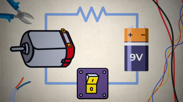
Notice that we connect the switch to the red cables and not the black. That is standard practice aimed at minimizing the points through which power can accidentally be connected to other electrical components. Stopping the power near its source is the best way to do it.
Connecting the other side of the motor directly to the battery will turn it on, but we want a way to control when we turn it on without having to disconnect and reconnect cables constantly. For that reason, we added a switch between one of the connections from the motor to the battery. It may seem easier to use a larger switch, but the DIP switch is meant to be soldered to a PCB, and that is what we'll do in the end.
It doesn’t matter if you connect the wire to the positive (cathode) or the negative (anode) terminal of the battery.
Note that for power sources, the cathode and anode are marked opposite to that of diodes and other electronics. In them, the cathode is the positive terminal and the anode is the negative one.

Here’s a list of all the tools you’ll need to build the DIY Rotating LED Clock Display. Each tool links to Amazon. If a link isn’t available, we’ve included tips on how to find another one.

Here’s a list of all the parts you need to build the DIY Rotating LED Clock Display. Each part links to Amazon. If a link doesn’t work, don’t worry - we’ve also added tips on how to find a replacement.

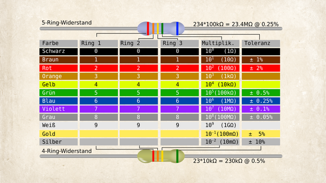
Resistors are essential electronic components that limit the flow of electric current in a circuit. Because they’re so small, their resistance value (measured in ohms, Ω) is usually marked with colored bands instead of numbers. Here's how to read them:
It is part of the Functions block, but what does it do?

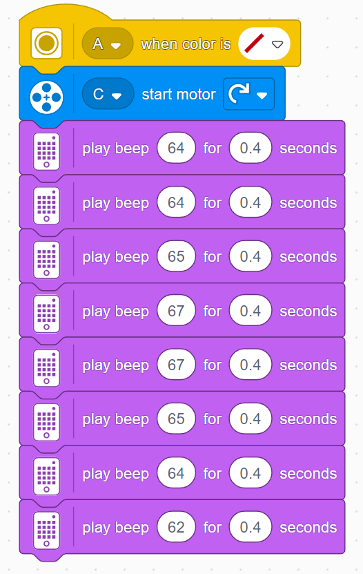
Due to the long construction, you need to be careful with time in this lesson. Don’t let the students spend too much time building. If you think you can manage it, you may let them find their own sheet music and adapt it, but we recommend sticking to the short section from Ode to Joy as shown in the tutorial. This melody also serves as preparation for the next lesson, where a ready melody will again be needed. Here’s what the program looks like:
Because this is the musical level, it’s important to set some rules for the sounds the robots make. Students often don’t realize how loud it can get, so remind them to keep the volume lower so they can hear the hubs, and to stop their programs in time, since continuous sounds can become quite loud.
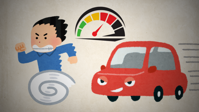
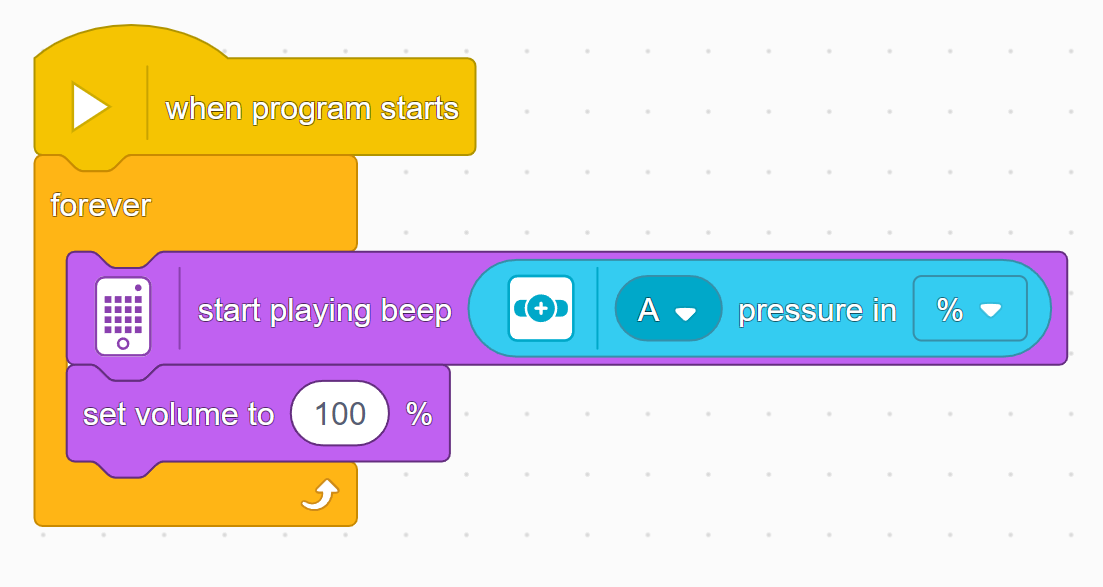
In this lesson, students will learn many of the key concepts needed for the rest of the course. That’s why there is little construction and mainly exploration with a single force sensor. Make sure they understand the difference between pitch and volume. Although there are many new blocks introduced, they are mostly simple and similar to previous ones. These blocks will also be used in many future lessons, giving students plenty of time to become familiar with them. By the end of the lesson, students should have tried the following two programs:
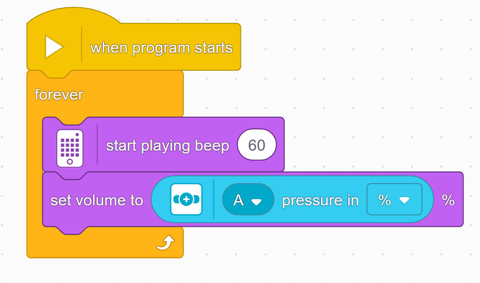
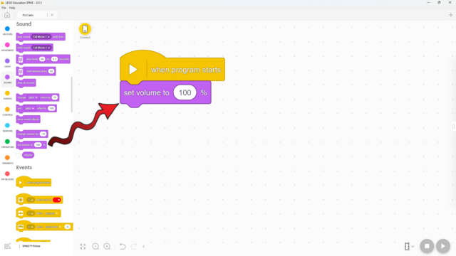
A big part of a sound is its volume. Here's how to change it!
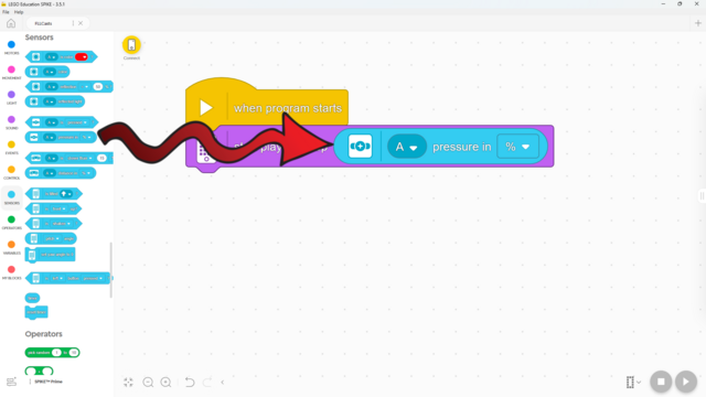
The force sensor can detect how hard it’s being pressed! Here’s how:
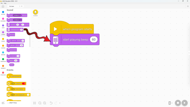
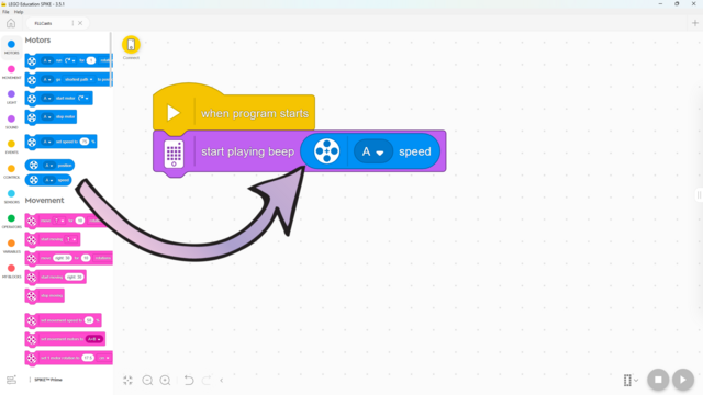
Did you know that your hub can play a sound? Here's how!
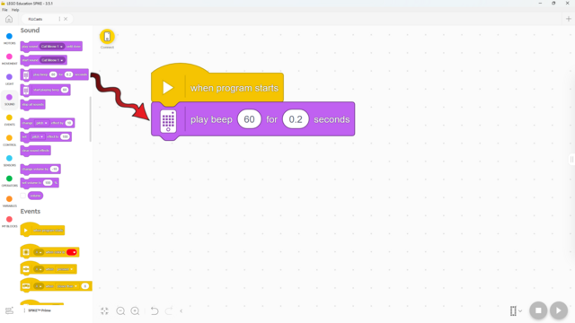
Did you know that your hub can play a sound? Here's how!
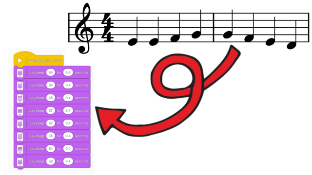
Have you ever wanted to program your favorite music on SPIKE Prime? Here's how!
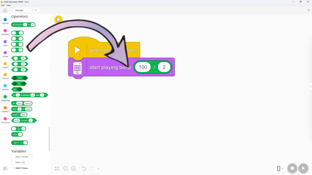
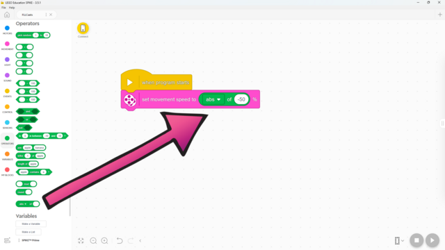
You already know how to do division in mathematics - here’s how to do it in SPIKE Prime!
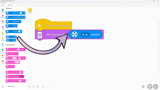
Did you know you can use the motors as sensors? Here's how!
Did you know you can use the motors as sensors? Here's how!