
Warehouse Мission Рules
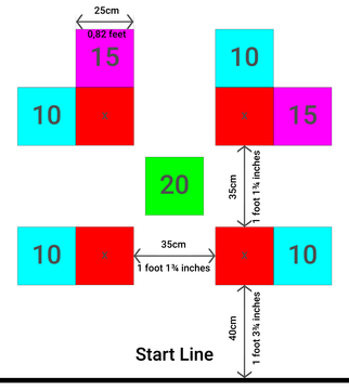
Below is an example of a robot competition field along with the scoring system used to evaluate performance.
- #2606
- 25 Mar 2026
This page shows all the robotics tutorials listed without specific grouping. Each tutorial is short, on specific topic, has a video. Tutorials are structured in sequence in Courses.
Below is an example of a robot competition field along with the scoring system used to evaluate performance.
![]()
Variables are like small boxes inside the computer that store important information for us. Imagine the following situation:

Here you can find a cheat sheet with the most commonly used commands. There are also more advanced commands that are not included in the built-in API, but the available ones cover most, if not all, of the students’ needs.
Below is an example of a function definition and how to read it:
move_for_degrees(pair: int, degrees: int, steering: int, *, velocity: int = 360, stop: int = motor.BRAKE, acceleration: int = 1000, deceleration: int = 1000) → Awaitable
...
Parameters
pair: int
The motor pair to be used.
degrees: int
The number of degrees the motors should rotate.
steering: int
The steering value (from -100 to 100).
Optional keyword arguments:
velocity: int
The speed of the motor in degrees per second.
...
stop: int
Defines how the motor behaves after it stops. Use constants from the motor module.
...
acceleration: int
The acceleration in degrees per second squared (1–10000).
deceleration: int
The deceleration in degrees per second squared (1–10000).
Let’s take a closer look at the function definition:
The parameters before the "*" symbol are required parameters. You must provide them in the correct order. For example, the first parameter is "pair", so the command expects the motor pair first. The same applies to "degrees" and "steering".
The parameters after the "*" symbol are optional parameters. To change them, you must use their names. This means you cannot just write a number - you need to specify which parameter you are changing. For example:
motor_pair.move_for_degrees(motor_pair.PAIR_1, 360, 0, velocity=280)
Finally, the "Awaitable" keyword means that this command can be used with "await". This allows the program to wait until the command has finished before continuing with the next one. For example:
await motor_pair.move_for_degrees(motor_pair.PAIR_1, 360, 0, velocity=280)

The await command tells your robot:
“Wait until this action is finished, then continue!”

Without "await", the robot may move on too quickly and not finish its actions properly.
You can only use "await" inside an "async" function.
async def main():
    await motor.run_for_time(port.A, 1000, 1000)

We already know how to set the speed of the motor and how long it should move. However, with these commands alone, we cannot control exactly how many degrees the motor turns. To make the motor turn a specific number of degrees, we need to use some simple math.

The motor speed is measured in degrees per second. We can use this to calculate how much the motor will turn using the formula:
S = V * T
S – the distance traveled (in this case, the number of degrees the motor turns);
V – velocity (degrees per second);
T – time (in seconds).
Before we can run Python programs on the robot, we need to open the SPIKE software, create a Python project, and connect the Hub to the computer. In this tutorial, you will learn how to do each of these steps using the LEGO SPIKE software.


During this course, we expect the following from you:
Ask questions when you are curious or need help.
Don’t be afraid to make mistakes - this is how you learn.
Share your ideas, help others, and be open to receiving help.
Listen carefully when the teacher is speaking - it’s important for everyone.
Read your lesson before coming to class.
The teacher does not expect you to know everything. What matters is that you ask when you don’t understand something. Go to your teacher when you need help - they can support you only if you ask.
It’s normal not to succeed the first time. Learning takes practice. Keep trying, testing, and improving your solution until you succeed.
The whole class is a team. Help each other, share ideas, and learn together. It’s okay to give hints or learn from others - this helps everyone improve.
When the teacher is explaining something, it is important for everyone. You might hear a solution to a problem you will face later.
You will have access to e-textbooks that you can read at home on a phone, tablet, or computer. Try to think about the tasks in advance so you are ready to work during the lesson.

In this course, you will work with other students in your group. These may be your classmates, teammates, or students you know from other activities. It is important to get to know your group so you can work well together.
Your teacher will introduce themselves first, and then you will get to know the other students in the group.
Remember your teacher’s name and address them by name.
Listen carefully to your classmates and pay attention to what they share. Show the same respect that you would like to receive.
Each student should share:
their name;
their age;
their grade;
the school they attend;
their favorite sport, hobby, or activity.
If your teacher allows it, you can also share a short story or something special you have done - for example, “I’ve done something you may not have done, which is…”.

In this self-paced, beginner-friendly online course, you and your child will learn how to create a rotating LED strip display—a glowing clock that seems to paint time in mid-air. And don’t worry if you’ve never soldered, wired a circuit, or touched an Arduino before. We guide you from the very first step all the way to powering on your finished display.
By the end of this journey, you’ll both have learned real hands-on skills—like how to solder, drill clean mounting holes, read resistor color codes, and work with common electronic components—all while building something that looks impressively “advanced” but is totally achievable for beginners.
Before you jump into the build videos, this first lesson gives you a clear picture of what you're creating—and what materials you’ll need to make it happen. We want you to have full confidence in what you’re investing in. There are no surprise expenses later: everything required is listed upfront, along with tips on where to buy each part.

The hall effect sensor can't detect a magnet, without there being one in the first place. While we can use glue or other ways of attaching a magnet to the clock face, we decided to use a second magnet on the other side of the face to hold the main one attached to it.
Make sure the connection between the clock arm and the clock's body is strong. Otherwise, it may sleep when you turn it on.
The 330 Ω resistor on the LED strip’s data pin acts like a tiny speed bump for the signal. It protects the LEDs by keeping the data signal from being too strong or too fast, which helps the strip work correctly and last longer.
The ground connection to the LED strip can be connected to any ground connection of this circuit. There is no danger of anything burning.
Be careful with the power connection of the LED strip. If you connect it to the 9V battery line, it will fry the LED, and the strip will be ruined.
Measuring the center of mass of the arrow arm, in its unfinished form, will be inaccurate, but we can come closer to being accurate if we place as many of the components on it before making our guess.

A pull-down resistor keeps the Hall sensor’s signal at zero when no magnet is near. Without it, the sensor could get confused and give random on/off signals. It makes sure the circuit can clearly tell when a magnet is present or not.
A Hall effect sensor is basically a tiny magnet detector. When a magnet comes near it, the sensor can “feel” the magnetic field and tell the circuit, usually by turning its output on or off. We can use it to detect things moving, like wheels spinning or doors opening.
Some microcontroller pins can act like tiny batteries (power) or tiny paths to ground. By setting a pin HIGH, it gives a little voltage to power something. By setting it LOW, it acts like ground, letting current flow back. This is useful for testing or powering small sensors,
In short: Hall sensors feel magnets, and digital pins can sometimes act like tiny power sources or grounds to help run them.

Some LED strips have a sticky backing covered by a thin plastic layer. You can peel it off and stick the strip directly. If your strip is different from the one we suggested in the shopping section, you might need to get a little creative.

While we can pass the cables around the PCB, we decided that it would look more appealing if they were to pass from underneath the PCB. While this is an easy way to do so, those more tech-savvy can solder 3 terminal blocks to the PCB, as a way to bypass the drilling task and create an easy way to replace the LED strip in the future.
