
How to fix the circuit components in place - part 1
time to plan where everything on the PCB will go. You can rearrange the components as you wish, as long as the wire connections are done correctly after that.
- #2519
- 07 Nov 2025
time to plan where everything on the PCB will go. You can rearrange the components as you wish, as long as the wire connections are done correctly after that.
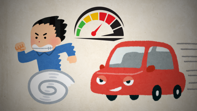
If you’ve connected everything correctly, you can now turn on the motor and control its speed using the potentiometer.
The potentiometer is the small knob on the motor speed controller that you can rotate.
Time to make the final connection and complete the prototype.
To demonstrate that it does not matter where in the circuit we place the switch, we placed it at the negative battery terminal. However, in practice, it is always better to put it near the positive terminal as it lowers the area that can damage your electronics if accidentally touched by other power sources or grounding.
You can notice that the two positive terminals are placed in the middle. That is a common practice that has a few functionalities, like shortening the paths on the PCB, but the main purpose is to lower the chance that the power cables connected directly to the battery are more difficult to touch accidentally.
The motor’s contacts are connected by a wire that is wrapped in a special way. When electricity flows through the wire, it creates a magnetic field that makes the shaft spin. The direction the shaft spins depends on which way the electricity flows. If you switch the wires, the shaft will just spin the other way, and nothing bad will happen. The plus (+) and minus (–) marks on the motor only show which way to connect it if you want the shaft to spin in a certain direction.
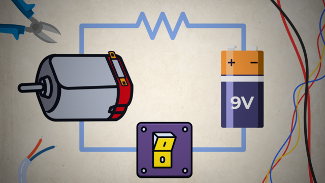
Notice that we connect the switch to the red cables and not the black. That is standard practice aimed at minimizing the points through which power can accidentally be connected to other electrical components. Stopping the power near its source is the best way to do it.
Connecting the other side of the motor directly to the battery will turn it on, but we want a way to control when we turn it on without having to disconnect and reconnect cables constantly. For that reason, we added a switch between one of the connections from the motor to the battery. It may seem easier to use a larger switch, but the DIP switch is meant to be soldered to a PCB, and that is what we'll do in the end.
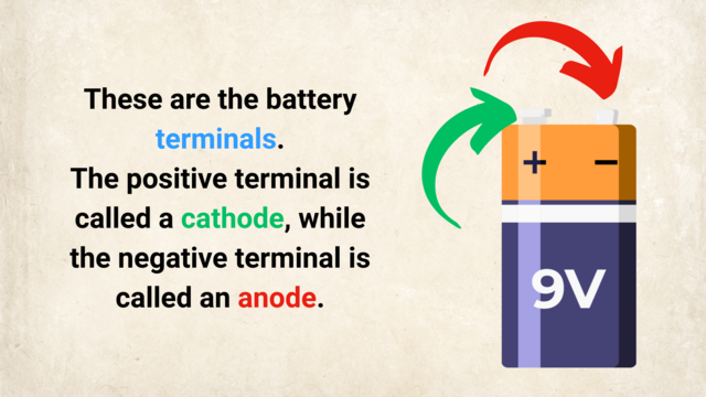
It doesn’t matter if you connect the wire to the positive (cathode) or the negative (anode) terminal of the battery.
Note that for power sources, the cathode and anode are marked opposite to that of diodes and other electronics. In them, the cathode is the positive terminal and the anode is the negative one.

Here’s a list of all the tools you’ll need to build the DIY Rotating LED Clock Display. Each tool links to Amazon. If a link isn’t available, we’ve included tips on how to find another one.

Here’s a list of all the parts you need to build the DIY Rotating LED Clock Display. Each part links to Amazon. If a link doesn’t work, don’t worry - we’ve also added tips on how to find a replacement.

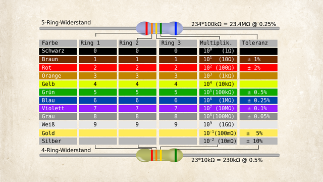
Resistors are essential electronic components that limit the flow of electric current in a circuit. Because they’re so small, their resistance value (measured in ohms, Ω) is usually marked with colored bands instead of numbers. Here's how to read them:
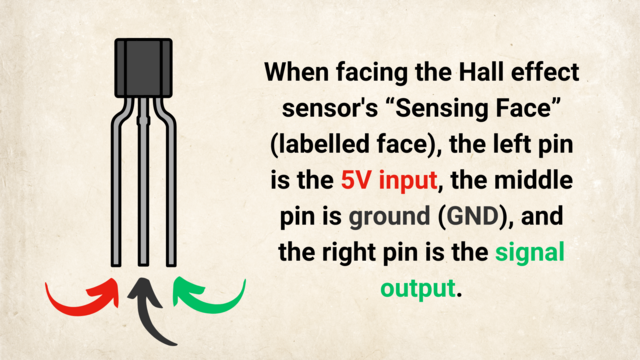
What Is a Hall Effect Sensor?
A Hall Effect Sensor is a small electronic component that detects magnets. When a magnet comes close, it sends a signal to other devices, like an Arduino or an LED light. Think of it as a tiny switch that turns on whenever a magnet is nearby.
If you don’t rotate an object around its center of mass, it becomes unstable - causing vibrations, extra stress, and sometimes complete system failure.
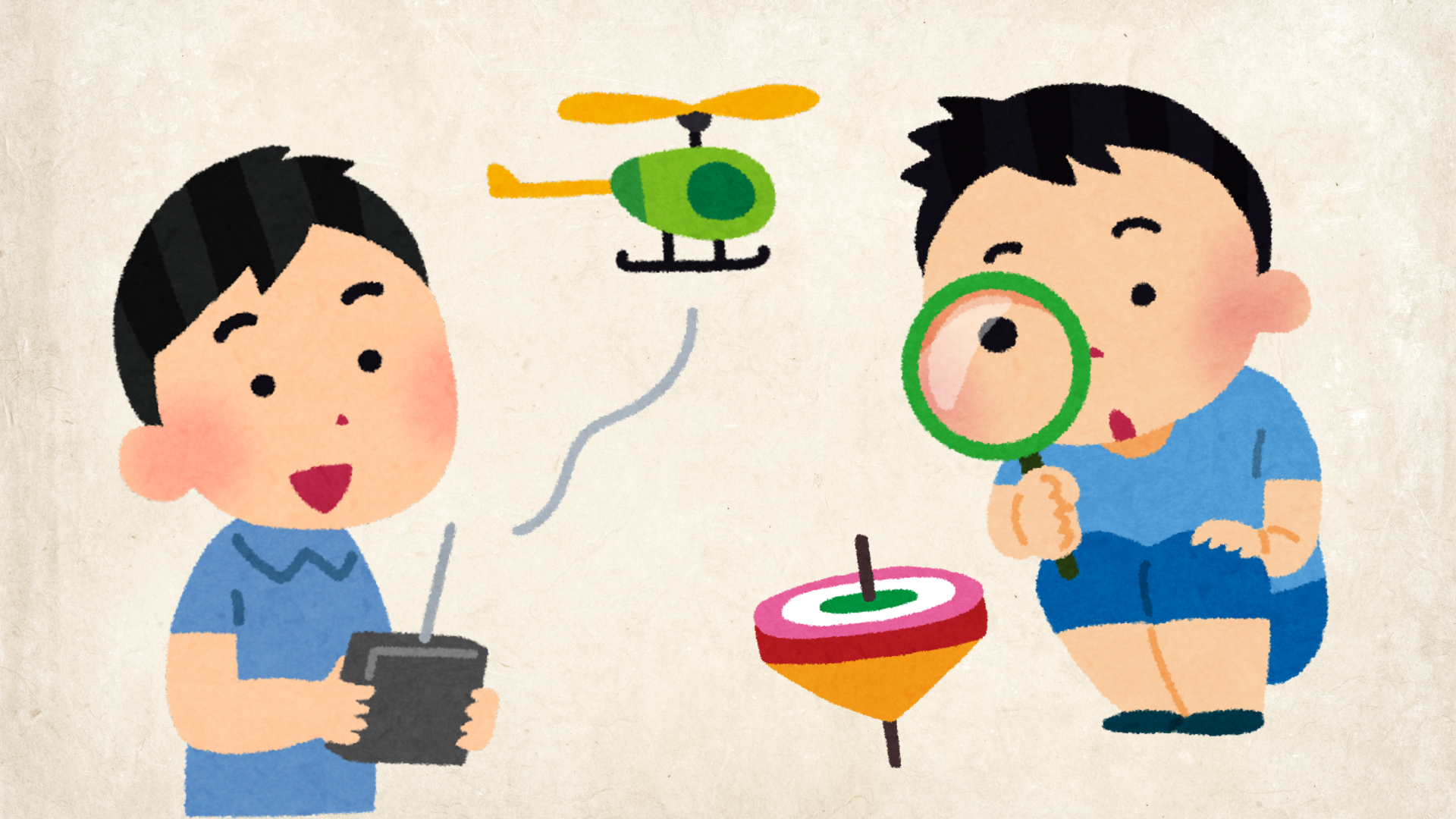

You’ve probably seen a spinning fan or display with LED lights that forms text or images in mid-air — it looks like magic! But what’s really happening?
This amazing effect is based on a concept called Persistence of Vision (POV). When an LED strip spins fast enough and its lights turn on and off at just the right times, your brain blends those quick flashes together. The result? You see a complete image - even though it’s really just a single line of lights moving in circles!
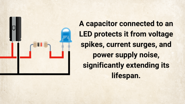
What is a Capacitor?
A capacitor is an electronic component that stores electrical energy in an electric field. You can think of it like a tiny rechargeable battery, but it charges and discharges much faster and can’t hold energy for very long.
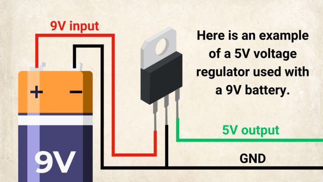
Why Are Voltage Regulators Important?
They protect components from getting too much or too little voltage.
They keep the power supply stable.
They make electronic devices more reliable and last longer.
Tools & materials needed for drilling.
Step-by-step drilling technique.
How to keep yourself safe in the process.
Here, we’ve listed all the tools and skills you need to solder and desolder components using THT (Through-Hole Technology).
Before you connect wires in your project, you need to take off the plastic covering (insulation) at the ends so the metal wire is exposed. This is called stripping the wire. You can do it with a wire stripper or even with simple tools you may have at home.
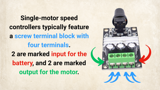
In the image below, you'll see where to connect the power source and the motor to the motor speed controller.
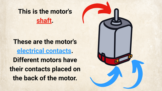
In the image below, you can see the "electrical contacts" of the motor pointer with blue arrows.

We are about to connect the whole car with the lights and motors to the controller. Let's recap to know what is ahead of us, what would the process be and what is the end result of the next couple of sections when at the end we have a car controlled by the phone

The power in the car comes from the batteries. The batteries are in a batteries holder. About 5 of them. Two cables are connected to the batteries holder. It is very important to identify which of those cables is the plus and which is the minus.

We would start connecting a lot of things to the Raspberry Pi. It will be good if we could have some way of referring to the pins on the Raspberry Pi. For example like Pin 5 or Pin 26. Luckily there is such a way.

In the set for the Perfect Course, you have 3 different type of cables. They are called Breadboard Jumper Cables. We would need to use them to extend the default cables on the car and to connect the car components to our new controller