
How to Drill Small Holes
What You’ll Learn:
Tools & materials needed for drilling.
Step-by-step drilling technique.
How to keep yourself safe in the process.

- #2488
- 10 Sep 2025
Tools & materials needed for drilling.
Step-by-step drilling technique.
How to keep yourself safe in the process.
Here, we’ve listed all the tools and skills you need to solder and desolder components using THT (Through-Hole Technology).

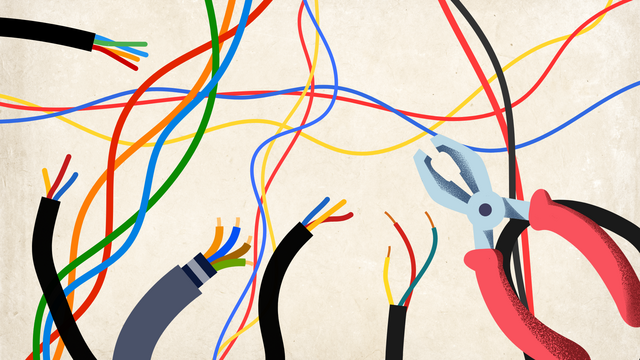
Before you connect wires in your project, you need to take off the plastic covering (insulation) at the ends so the metal wire is exposed. This is called stripping the wire. You can do it with a wire stripper or even with simple tools you may have at home.
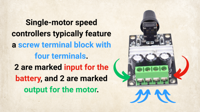
In the image below, you'll see where to connect the power source and the motor to the motor speed controller.
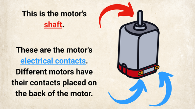
In the image below, you can see the "electrical contacts" of the motor pointer with blue arrows.

We are about to connect the whole car with the lights and motors to the controller. Let's recap to know what is ahead of us, what would the process be and what is the end result of the next couple of sections when at the end we have a car controlled by the phone

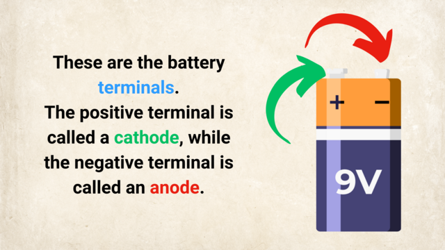
The power in the car comes from the batteries. The batteries are in a batteries holder. About 5 of them. Two cables are connected to the batteries holder. It is very important to identify which of those cables is the plus and which is the minus.

We would start connecting a lot of things to the Raspberry Pi. It will be good if we could have some way of referring to the pins on the Raspberry Pi. For example like Pin 5 or Pin 26. Luckily there is such a way.

In the set for the Perfect Course, you have 3 different type of cables. They are called Breadboard Jumper Cables. We would need to use them to extend the default cables on the car and to connect the car components to our new controller

We need to extend the cables to be able to connect them to our Raspberry PI. We must also add new connectors at the end of the cables.

Every electronics tutorial, book or course about Raspberry Pi or Arduino will use a motor driver. Very few of the courses will actually explain why do you need a Motor Driver, what is it for?

Give it a name and you will have power over it. I learned this from an MIT professor. So let's give the part of the car names. Then we could refer to them. Talk to them. Change them. Do all kinds of things with them. Give it a name and you will have power over it.
The course is designed to be used with almost every remote controlled car. The process of opening the car will be different for different cars but there are basic principles that you could follow.

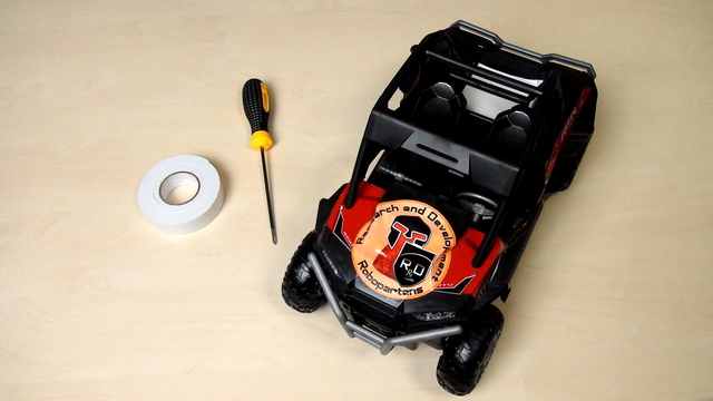
This is a remote control car. Have fun with it before disassembling it.

The course is very suitable for students and you don't have to buy a new set for each student. You can group them, divide them, organize the use of the sets and you could technically work with 70-80 student with only 6 sets.

Time to experiment with the controller, the diode and the program that makes the diode blink. Don't be afraid to change the program. We've prepared a number of tasks for you in the course that you should definitely complete before moving forward.

In this episode we would modify the blinking diode program so that the diode will stay on for four seconds.

Safety notice: There is current flowing in this device and you can touch the device with your bear hands. This is not dangerous, but there are a few things that you should consider especially in class.

As a result from the previous two videos we have a diode that is blinking. What will now happen with the diode if we remove the power and change the position of the legs.

To correctly upload the blinking diode program to the controller we must first check some of the configurations of software. These are the "selected controller" and COM port

For making the diode blink we just use one of the examples available in the Arduino Software.

Arduino programs are developed with a software and this software is downloaded from the http://arduino.cc site.

Developing a program for the Arduino is very easy. We need to do again three thigs:

You have the controller, you have the diode. The controller has a number of pins (holes). Where should you put the diode so that it starts blinking?
The small holes on the controller are called pins. On our controller we have 32 pins. The more pins that you have, the more elements you can controller with this microcontroller. For this video the interesting pins and 13 and GND

For the current specific example we need two parts - the diode and the controller. In this episode we would show you which part is the controller, which are the jumpers and finally we would choose a diode.

Why: It's an easy and fun example to introduce you to Arduino
How: Presenting questions and trying answer this questions. Experimenting with different tasks.
What: We would like to show you how to control a diode. We would build a device and write programs for this device.
End Result: A blinking diode