
Task - Calibrate more than one sensor with the Advanced Calibration technique
Following the previous tutorials from the course, implement the calibration of the minimum and maximum values.
- #640
- 04 Oct 2017
Following the previous tutorials from the course, implement the calibration of the minimum and maximum values.


As an exercise try to implement the calibration of the minimum and maximum values for a single sensor.

Implement the program for array initialization.
Follow the video tutorials for initializing arrays and implement the program.

Many times we just upload blocks and leave it up to you to use it. In this tutorial, I would like to show you how to use the implemented blocks. How to import them into the EV3-G software. How to see them in the palette. How to drag and drop them to build a working program.

Following the Advance Sensor Calibration course section, we found the min and max values detected by each sensor. Now it is time for the real deal of the calibration. Detect the current value from the sensor and find what is the percentage of this value for the range between min and max.

In the course section for Advance Sensor Calibration we previously showed you how to find the minimum and maximum value for a single LEGO Mindstorms Color Sensor and to store this value in an array. The program was implemented with the EV3-G software. In this tutorial we are going to find the Min and Max for all the four sensors and to store all the 8 values in an array.

In this tutorial, we would implement a program that finds the minimum and maximum value detected by the sensor and stores this two values in an array.

"Array initialization" is the first step in every program that involves Arrays. This applies to most programming languages and for EV3-G it is a must.
In this tutorial, we would show you how to initialize the array and how to extract this logic in a new block
Would you like to resolve all the problems with the light/color sensors that you have? And to make all of them work in a predictable, stable way even when using more than one MINDSTORMS colour sensors.
When using Color sensors it is important to calibrate them depending on the light conditions in your venue. In this way, the calibrated sensor will show values between 0 and 100 independent of the light conditions. But using the default EV3 colour calibration available in the colour sensor block could lead to unpredicted problems that are difficult to track and resolved especially when used with multiple Color sensors. So in this series of tutorial we implement the calibration ourselves discussing the principles of colour sensor calibration.

Building a rack is a very important skill during competitions. You should try to build one, learn how to use it and have it as a tool for you next robots. But for this particular BoxRobot, we will not continue with a rack.

Using the rack depends on the experience of the team. Based on this a different number of gear wheels and racks would be used.

Build a rack and try to lift the robot with this rack.
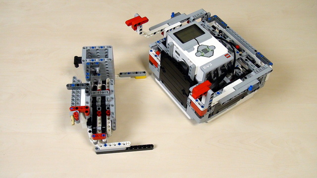
The next step of lifting a robot to a mission model is to try to use a rack.

Think of an attachment that leaves the Gecko on the mission model. Don't use the robot attachment that we already have. Just the box robot and the gecko. Nothing should support the Gecko when it is hanged on the mission model.

In this tutorial, we add another mission to our current program. This mission is - hanging the Gecko from the FIRST LEGO League Animal Allies.

What should you as a teacher know when the students are trying to achieve a program and robot attachment that could reproduce their behaviour 9 out of 10 times.

The task in this tutorial is to execute the program 10 times and to do it yourself. If you have your attachment then use it. If you have our attachment then use it. But execute the program 10 times and make sure that it works.

How great is the great attachment for lifting that we built in this course? How many times can it lift the robot without making an error? How great are your attachments and how could you test them? - the answer is simple. Just try 10 times and they should work at least 9 of them as our attachment is.

If you've done the calculation following the previous tutorials you would arrive at a result of 18.75 rotations. But this is not the correct answer. The calculation is wrong, because the math model that we've built, although kind of obvious, is not correct. When experimenting the correct number of rotations would be 37.5. This is a large difference. Two times larger. Exactly two times large. Something should be happening here - and this thing is "planetary mechanism"

This is a teacher's note about the math behind calculating gear ratios with for our lifting attachment. It math model we build in previous tutorials is not exactly correct and here is the explanation why.

Connect the attachment to the box robot and find the correct number of rotations of the middle motor that would bring the robot up and forward and would attach it to the mission model.

Sometimes the answer that you get by calculating seems not to be right. Is it the calculation that is wrong. Probably it is not the calculation, but something is happening with the robot.

In the previous video, we found the correct answer for our task and it is 18.75, or is it?

What should you do as a teacher when the students are calculating the gear ratios and number of needed rotations?

Calculate the number of rotations you have to do with the motor to rotate the final small 8 teeth driving gear wheel to 1.25 rotations?

