

Improving FLL Robot Game. Teacher's Note. 9 out of 10 experiments
What should you as a teacher know when the students are trying to achieve a program and robot attachment that could reproduce their behaviour 9 out of 10 times.
- #479
- 15 Apr 2017
What should you as a teacher know when the students are trying to achieve a program and robot attachment that could reproduce their behaviour 9 out of 10 times.

In this video we discuss the durability of the construction of LEGO robots and how do we make them more durable.
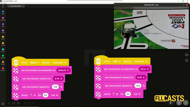
In this video tutorial we are demonstrating the impact of slow and fast acceleration on the robot. In the Scratch program there is an acceleration block for fast and slow acceleration. The robot behaves in different way. Let's explore them so that you know what to use for FIRST LEGO League competitions.

In this video tutorial, we demonstrate how to release the cargo of a mission model. This mission model is an Airplane. We have to push a lever down to release it. We use an active attachment with a gear wheel.

This animation demonstrates the use of a Grab Attachment build from LEGO Mindstorms Robot Inventor 51515 set. Many of the FIRST LEGO League missions could be accomplished by grabbing the mission model and the principles shown here is useful for mission models that look like a loop

In this video tutorial we accomplish the basketball mission from the FIRST LEGO League 2020 reply competition. We use the LEGO Education SPIKE Prime competition robot called Gazon. You will learn the principles of accomplishing a mission of two parts - put the ball in the basket and lift the basket.

This video tutorial is part of the 10 out of 10 series at FLLCasts and we will demonstrate how to accomplish the FIRST LEGO League 2020 RePlay competition mission called Innovation Project. Our goal is to push the construction to the require place on the field. What you will learn with this tutorial is how to place a random construction in the base and push/pull it to a place on the field 10 out of 10 times.

This is a video tutorial on accomplishing M12 and M13 of the FIRST LEGO League 2023-2024 MASTERPIECE Challenge. We've decided to combine the two missions and approach M12 in a slightly different way - by activating a gear wheel and thus rotate the chicken. The mission is accomplished in almost no time and the result is flawless. The robot is Chain Monster, a powerful LEGO Education SPIKE Prime robot.

In this video tutorial we take a next step in programming reliable and consistent robots and this is to learn how to stop at a second intersection. We need this because most of the time when we want to reach a mission model on a robotics competition field, the model will be located away from us and we must use all kind of technique to reach it. In this tutorial - we stop at a second intersection.

One of the smartest things you could do in any software program is to extract logic in small reusable, simple, understandable units. In EV3-G these are called Blocks and we are going to extract the logic for finding a minimum and maximum for each of the sensors in a new block.

A common question is how to display arrays on the LEGO Mindstorms EV3 brick screen. Displaying values from an array is not different from any other display operation. In this tutorial, we would look at displaying two specific values. The minimum and the maximum for a specific sensor from the Advance Calibration Course Section

What should you do as a teacher when the students are calculating the gear ratios and number of needed rotations?

Following the Advanced Sensor Calibration course section, it is time to extract the logic for getting a calibrated value into a new block. This block will have an input and on this input, we give the port number. The block will return the calibrated value for this port number. We've built all the other blocks only because of this almost final video here.

This is a 10 out of 10 tutorial demonstrating the consistency and reliability of a LEGO Education SPIKE Prime robot when the robot delivers a mission model to a specific position on the field.

In this video tutorial, the Chain Monster box robot accomplishes three missions in a single run from the FIRST LEGO League 2023-2024 MASTERPIECE Challenge season. The LEGO Education SPIKE Prime robot uses an active attachment to collect the mini figures, to push a lever, and to deliver the figures to their designated places. The robot starts from the red base and returns to the blue base, performing all these actions in less than 20 seconds - consistently and reliably.

In this tutorial, we show you how to display all the values from an EV3-G array on the EV3 brick display. We are using an array Read Operation along with a loop. We are also detecting the loop counter and using it as an index to an array. It's basically the only viable way to do it. The process is commonly referred to as - "Iteration over an array" (although we still do not have an iterator in the programming language, we promise that one day we would do the super advance videos on "iteration" using the LEGO MINDSTORMS robots")

In this LEGO video tutorial we accomplish 3 missions with the Kriket box robot. A number of actions are performed like Lever, Lift, Drop, Pull, Align. This tutorials shows how to accomplish missions models that are closely positioned next to each other.

In this video tutorial we deliver the Innovation project model from base to the cargo connect marker on the field. The goal of the mission is to deliver. The mission model is assembled before that.

Throwing/Shooting is a common challenge in FIRST LEGO League competitions and in this robotics video tutorial we are demonstrating an attachment that you can use to throw/shoot a ball. There have been missions for throwing balls like in bawling, or like in soccer/football. The attachment that we use relies on the properties of the plastics used for the LEGO MINDSTORMS Robot Inventor 51515 set - it bends and it throws.

The dance mission is one of the most straightforward and easy missions to complete at the FIRST LEGO League competitions. This one is from RePLAY competition. The goal is to reach a specific place on the field and dance with the robot. You will see how we dance and have fun with our robot. Never forget to have fun during the competitions.

Note for the teacher on making the construction more stable, more durable and using beams for this.

This video tutorial contains a detailed explanation on how we accomplish the FIRST LEGO League 2018-2019 Into Orbit mission called M05. EXTRACTION, but compared to one of the other tutorials about this mission, in this specific tutorial we are using Box Robot 1 and a multi-purpose attachment. The attachment is designed for two missions and one of the missions is the Extraction

In this video tutorial, we focus on M10 of the FIRST LEGO League 2023-2024 MASTERPIECE Challenge competition. We use the Chain Monster, a LEGO Education SPIKE Prime robot, equipped with a three-axle attachment. The mission's objective is to lift the sound mixer sliders and position them precisely to score the maximum points. While the mission may seem challenging at first, once you understand how the attachment works and how to properly connect it to the robot, it becomes a breeze. Let’s give it a try!

This is a 10 out of 10 tutorial where we deliver and drop precisely to complete a FIRST LEGO League 2021-2022 Cargo Connect mission. We reuse the same attachment as in other missions to demonstrate a reusable attachment.

This is a 10 out of 10 tutorial that demonstrates the consistency and reliability of the robot to complete the Unused capacity mission. In this mission, we do not need any guidance to push the model as it is near the west side where it should arrive.

Energy storage mission from FIRST LEGO League 2022-2023 is again a two parts mission where we have to drop a few energy units in the mission model, but we also have to pull part of the mission model. In this video tutorial we demonstrate how the Chain Monster LEGO box robot accomplishes this with a multi purpose attachment for box robots.
