So far, we’ve explored a line-following algorithm commonly referred to as duck walking. Let’s take a closer look at how it works and consider how many distinct states it actually involves.

To access the full video please subscribe to FLLCasts.com
- #885
- 30 Mar 2018
The line-following program that implements the duck walking algorithm looks like this:

It consists of two basic states:
- If the color sensor reads black, the robot turns in one direction;
- If the color sensor reads white, the robot turns in the opposite direction.
As you can imagine, this approach isn’t very efficient. The robot is constantly switching between left and right turns, and never moves straight forward—even when the line is perfectly straight. This makes the movement slow and inefficient. In this example, we assume the robot is following the right edge of the black line.
So, how can we improve this? One idea is to introduce a third state where the robot moves straight ahead. The improved model would have three states:
-
Turning left – when the robot is outside the line:

-
Turning right – when the robot is over the line:

-
Going forward – when the robot is right on the edge of the line:
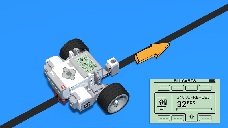

To implement this, we need to stop using the color mode of the color sensor and switch to reflected light mode. This mode returns numeric values based on how much light is reflected off the surface under the sensor.
Let’s say we’ve measured the reflected light values in each zone:
- Over the black line → 9
- Over the edge of the line → 32
- Over the white area → 55
Programming the robot to go forward only when it reads exactly 32 isn’t practical. Instead, we allow some margin of error. Let’s say we accept values between 27 and 37 (±5 from 32) as "on the edge". So:

- If the value is less than 27, the robot is on the black line and should turn right.
- If the value is between 27 and 37, the robot is over the edge and should go forward.
- If the value is greater than 37, the robot is in the white area and should turn left.
The full decision logic for the improved algorithm looks like this:

Try measuring the values your robot reads over the black line, the edge, and the white area. Then implement this three-state algorithm. Break it down into smaller, manageable tasks and test each part as you go.
Courses and lessons with this Tutorial
This Tutorial is used in the following courses and lessons
Instructors Remote Training
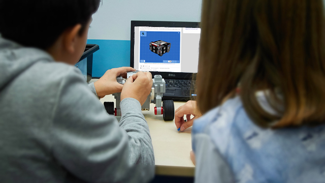
If you are working with students and you want to introduce Robotics to your class or you want to mentor a FLL team, but you are insecure about your technical knowledge in the Robotics field, then this is the right place for you. Having in mind teachers' busy schedule, we have design two different schedules and added an option to design one just for you. FLLCasts's Mindstorms EV3 Robotics Online Training is the perfect match for any teacher.
After the completion of each task the participant has to upload his solution for verification.
- 183
- 280:11
- 156

Competition programming
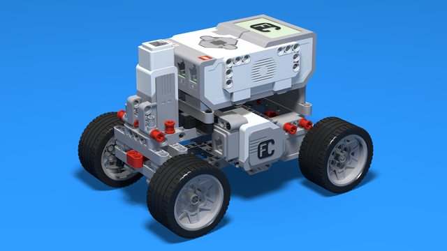
In this episode, we introduce a LEGO Mindstorms EV3 version of competition robot construction. It is a modular construction, with medium motor for additional attachments and two light or colour sensors for orientating on the field.
- 7
- 0
- 8
- 3d_rotation 1
Robotics with LEGO - Level 2.0 - Robots in Factories
The third level of the Robotics with LEGO curriculum for students from fifth to twelfth grades.
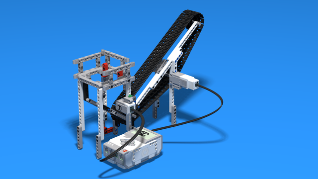
Robots in this level use two or three sensors at a time and students create more complex programs for them. The work of the differential and its usage in vehicles with one drive motor is explored. Robots interact with each other and transfer information or material between themselves. Students learn in depth how to create smoother line-following programs. In the end of the workday, robots leave the conveyor belt and relax with a recreational game of volleyball.
- 44
- 15:01
- 129
Additional tasks for the warehouse robots
It appears we have more time to work on improvements
- 2
- 1
- 3
- 3d_rotation 0
Level C1. "Transportation". Robotics with LEGO
This is the fifth level in the Robotics with LEGO curriculum for students in third or fourth grade.
For the first time robots with steering wheels are built in this level. Those robots use one or two drive motors. The work of the differential and its usage in vehicles is explored. Students learn in-depth the working of the light sensor to create better line-following programs. The first two-wheeled motorcycle-robot is built.
- 33
- 1:03
- 110

Lesson 5 - Boat for line following with 3 states
Remember to provide feedback to students regularly. It's important to give structured feedback in the form of a grade. Today, you'll need to grade your students following this article.
- 5
- 3
- 8
- 3d_rotation 1
Robotics with LEGO - Level 2.0 - Robots in Factories
The third level of the Robotics with LEGO curriculum for students from fifth to twelfth grades.
Robots in this level use two or three sensors at a time and students create more complex programs for them. The work of the differential and its usage in vehicles with one drive motor is explored. Robots interact with each other and transfer information or material between themselves. Students learn in depth how to create smoother line-following programs. In the end of the workday, robots leave the conveyor belt and relax with a recreational game of volleyball.
- 44
- 15:01
- 129
Lesson 5 - Robo Car
Remember to provide feedback to students regularly. It's important to give structured feedback in the form of a grade. Today, you'll need to grade your students following this article.
- 6
- 4
- 11
- 3d_rotation 1