

Completing the clock hardware - part 3
The ground connection to the LED strip can be connected to any ground connection of this circuit. There is no danger of anything burning.
- #2551
- 10 Nov 2025
The ground connection to the LED strip can be connected to any ground connection of this circuit. There is no danger of anything burning.
Be careful with the power connection of the LED strip. If you connect it to the 9V battery line, it will fry the LED, and the strip will be ruined.
Measuring the center of mass of the arrow arm, in its unfinished form, will be inaccurate, but we can come closer to being accurate if we place as many of the components on it before making our guess.
A pull-down resistor keeps the Hall sensor’s signal at zero when no magnet is near. Without it, the sensor could get confused and give random on/off signals. It makes sure the circuit can clearly tell when a magnet is present or not.
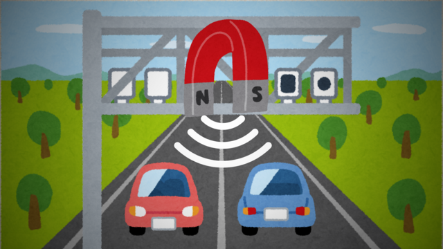
A Hall effect sensor is basically a tiny magnet detector. When a magnet comes near it, the sensor can “feel” the magnetic field and tell the circuit, usually by turning its output on or off. We can use it to detect things moving, like wheels spinning or doors opening.
Some microcontroller pins can act like tiny batteries (power) or tiny paths to ground. By setting a pin HIGH, it gives a little voltage to power something. By setting it LOW, it acts like ground, letting current flow back. This is useful for testing or powering small sensors,
In short: Hall sensors feel magnets, and digital pins can sometimes act like tiny power sources or grounds to help run them.

Some LED strips have a sticky backing covered by a thin plastic layer. You can peel it off and stick the strip directly. If your strip is different from the one we suggested in the shopping section, you might need to get a little creative.

While we can pass the cables around the PCB, we decided that it would look more appealing if they were to pass from underneath the PCB. While this is an easy way to do so, those more tech-savvy can solder 3 terminal blocks to the PCB, as a way to bypass the drilling task and create an easy way to replace the LED strip in the future.
On our LED strip, there are two extra wires for power and ground. We don't need them, so we cut them off. There is also an extra connector on the remaining cables. As we will be soldering them to the board, we don't really need this connector, so we remove it as well.
You’ll attach the lights to this stick, so choose its position carefully. Once the lights are attached, you can check where the center of weight is - that’s where you’ll mount the motor.
A capacitor acts like a small energy buffer. It stores a little electricity and releases it when needed. When the controller or LED strip suddenly turns on or changes brightness, it can briefly pull a lot of current. The capacitor helps by smoothing out these quick changes, keeping the voltage steady. This protects the controller and LEDs from sudden voltage drops or spikes and helps everything run more reliably. In simple terms, the capacitor helps keep the power smooth and protects the electronics.

If everything is connected correctly, the Arduino microcontroller will light up, powered with 5V from the 9V battery!
In a circuit, ground is the common reference point for voltage and the return path for electric current. After electricity flows through components, it needs a clear way to get back to the power source. All ground connections are tied together, so every part of the circuit shares the same reference point, and the current can flow in a complete loop. This helps signals stay consistent, and components work correctly. If the grounds were not connected, parts of the circuit could act unpredictably or not work at all. In simple terms, connecting all grounds keeps current flowing properly and the circuit working reliably.
Don't connect the voltage regulator to just any 5V pin of the controller. There must be a VIN pin, which is a dedicated powering pin for the controller. That is the pin through which you can power it with 5V, as it passes the power through a voltage regulator and other protections, which make sure the power is delivered safely.
If the battery holder already has such a cable attached to it, feel free to use it.
Be careful not to connect any other red power cables to the one leading to the battery, as it transmits higher voltage, which, while harmless to us, can still fry your controller and LED lights. Once you solder the connection between the battery and the voltage regulator input 9V terminal, connect everything else in this project to the regulator's 5V output pin.
The position of the voltage regulator won’t affect the balance much, so it’s best to place it near the DIP switch.
If the battery holder already has a cable attached, you can use that one.
The position of the DIP switch doesn’t affect the balance much, so you can place it wherever you prefer.
We'll be marking and drilling holes a few times during this course. If possible, it may be useful to set up a work desk for yourself.
Make sure to solder the breakaway headers at the correct distance from one another , so you can mount the controller on top of them. If you solder them too close or too far apart, desoldering the breakaway headers will be a harder task than what is meant for this course.
We use breakaway headers so our electronics can stay safe and flexible. They let us connect parts together easily, but also snap them apart later without hurting the circuit. This is helpful because we can test things, fix mistakes, or change parts without rebuilding everything. Think of them like LEGO pieces - they click together when we need them and come apart when we don’t.

Attaching the PCB to the clock face is best done with two sets of hands.
You need not confine yourself to the use of drawing tools. You can easily choose an image from the internet, print it out, and stick it to the clock surface. Or maybe you have other ideas of how to customise the clock face?
We used dental floss to draw lines from the clock face diagonals, and drilled the holes where those lines met.
You need not place the clock's arrow hole in the center. As this is a design choice, you can be creative and place it wherever you wish. You can even customise the shape of the clock face as well, so it is not a plain square like ours.

Don’t worry about which electrical contact you connect to the positive or negative output terminals of the speed controller. The cables can always be swapped later.
Do not solder anything to the speed controller.
You need a very short exposed wire to solder to the DIP switch. Try not to strip too much ot it, as it may come in contact with the other end of the switch, effectively bypassing it.